Formula Electric at Berkeley (blog work in progress)
- zhiyuan zhang

- Dec 6, 2021
- 6 min read
Updated: Sep 10, 2022
I am one the founding member and EECS sub team lead of Formula Electric at Berkeley (FEB)
FEB is an electric vehicle racing club that is going to compete in the FSAE student racing competition.
We build EV from the very scratch, and as one of the EECS member and the lead of the sub team, I am very proud of what we have achieved and what we are going to achieve.

I will be talk about 2 part of my work in FEB: individual technical work; leadership and teamwork.
Leadership and teamwork
As the sub team lead, I lead and oversee all the development for all the high voltage and low voltage system on the vehicle.
Here is an abstractive view of the HV powertrain. The accumulator, which is the battery pack will provide 600V and up to 80KW of power to the inverter, and the inverter will convert this DC current into 3 phase AC to power the Emrax 228 motor. The inverter we used is PM100DZ by Cascadia Motion. There are future plan of making out own in house inverter design, but as this is our first car, we decide to focus on other parts of the system. The motor is Emrax 228.

On the left side of last schematic is the accumulator (battery pack), which I will expand on.
Our accumulator is based on lithium ion battery cells. It is configured as 136s4p 18650 cylindrical cells. Which have a nominal capacity of 6.1kWh. The battery modules are separated into segments, each with 17s4p.
There are PreCharge and DisCharge circuit in the battery pack to ensure the safety of operation. Before the main relay close, there will be pre charge resistor charge up the capacitance in the motor inverter to ensure the peak current and voltage when the main relay closes is not too high, which might create arc and damage equipment. When the main relays are open, there will be discharge resistor discharge the entire system to burnout the excess energy stored in the capacitance of the system.
The total energy is measured by an energy meter, which is based on a shunt current sensor and few voltage measuring points. We utilize the multiple voltage measuring capability of the energy meter to determine the voltage different between the main relay, which will determine when is safe to close the main relay. There is also additional Hall effect sensor that will measure the current and is used for Brake System Plausibility Device.
Each paralleled battery model Is managed and monitored by a distributed BMS system.

We have a distributed BMS system, which I have great involvement of the design and development of the system.
We use LTC6811-1 BMS chip to do the balancing and sensor read out for the BMS. Each LTC chip is daisy chained together with isoSPI communication line. Thus we minimize wiring inside the battery pack, and this distributed daisy chain network of BMS allow us to scale the BMS very easily. There will be multiple daughter broad each with its own LTC chip, and they will share information on the isoSPI bus, and the command and computation of the logic is done in a centralized motherboard.
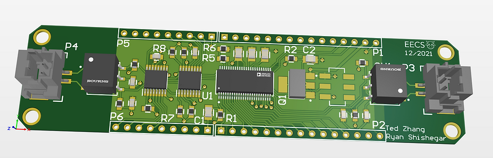
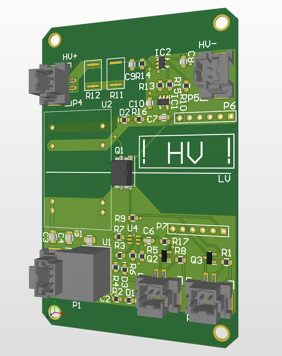
Below is the design of the current daughter broad. it only has the communication and control circuit on broad, this is because all the balancing circuit and temperature sensor readout circuit is on the auxiliary broad, which the daughter broad will be plug into. In this way, the auxiliary broad will make all the connection with the bus bar of the batteries and eliminate wiring, and it keeps the system modular, thus we can change the design of the auxiliary broad without redesign the daughter broad every time.
The daughter broad can balance 12 cells, take 12 voltage measurement, and have MUX circuit to measure 16 different input, which 12 will be used for temperature measurement for each battery module and 4 more for liquid sensor for sensing leak in the casing.
All the daughter broad runs on isoSPI and is powered by the battery they monitored, thus they are all isolated to each other, which prevent coupled failures.
Auxiliary broad test broad .

Old daughter broad design

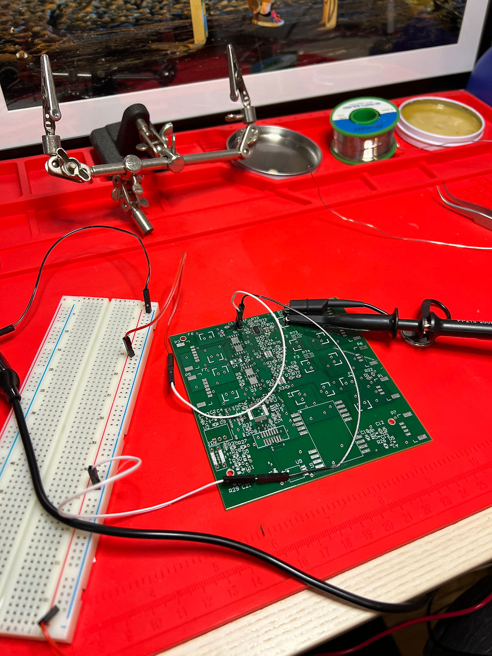
BMS Testing


There is a loop of shutdown circuit on the car that essentially act like a AND gate to all the safety critical monitoring systems. If anything is wrong, the shutdown circuit will open and open the main relay, which will shutdown the car. It includes switches that can be operated by driver or external person. It also includes isolation monitoring device which will monitor the isolation between the HV and LV system, inertial switch for detecting crash, Brake Plausibility Device for checking if the brake is operating normally, BMS for battery status, HV connector interlock to ensure the connection is secured.

There are also various other project in LV system which I oversees and advise
LV distribution broad ,which use hot swap controller to intelligently fuse the circuit, it will trigger a open circuit in over current situation much faster than fuse and have the ability to re try the circuit.
Driver interface, which have high brightness LCD screen, buttons, and switches for driver communication, status report and setup adjustment for the driver
Data logger and telemetry system, which stores data in emmc memory chips as well as SD card. The data is then being sent over 2 XBee transmitter for real time telemetry. We use 2 XBee because one runs on lower frequency, thus operate with better range and reliability. The other high frequency XBee have higher data transfer rate.
The data communication within the vehicle is accomplished using CAN bus, we have 2 CAN bus, one is dedicated for time critical and safety critical data, and the other one is fore data acquisition and backup.
All our broad with digital IO and processing need have STM32F446 MCU on it, which provide native support for ADC, DCA, digital IO, DMA, CAN, SPI, I2C, and URAT for our application.
There are more smaller project I will not introduce here.
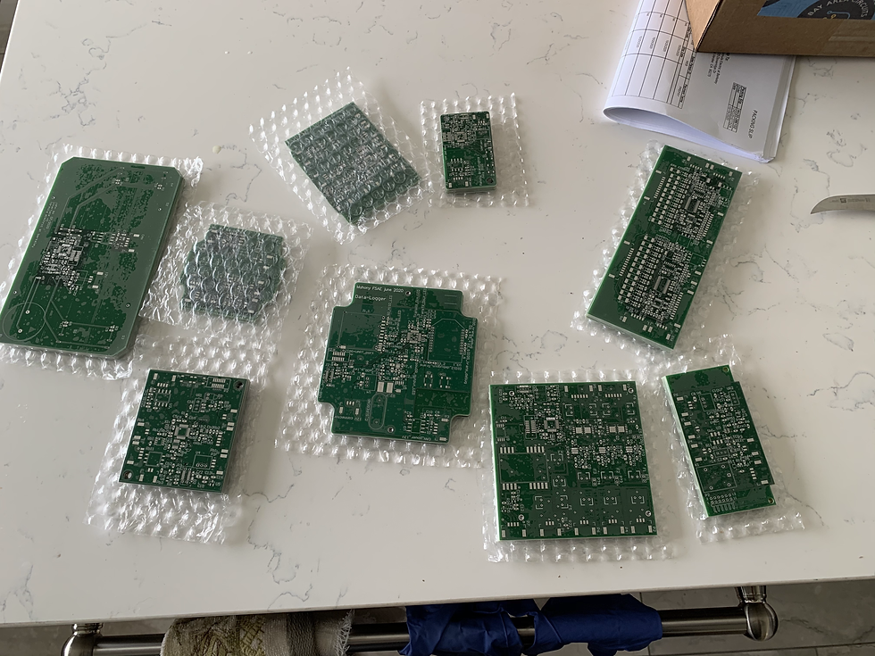
First iteration test broads
LVPDB test
CAN bus test runs

FEB EECS Subteam
Individual technical work
As a member of the team, I designed 3 circuit. Brake System Plausibility Device (BSPD), Accelerator Pedal Position Sensor (APPS), and help redesigned the Tractive System Activation Light (TSAL).
BSPD
Brake System Plausibility Device, which use analog circuit to check if the brake is pressed and there is current going in HV system. The purpose of this device is to prevent driver press 2 pedal at the same time and burn the motor, but more importantly it is to check if there is any malfunction of the powertrain system and if so, shutdown the car.
It uses a comparator to compare the output of brake pedal encoder to see if it is over a threshold,
It also have a comparator in the battery pack to compare the output of the Hall effect sensor and iff if it is over a threshold, if yes, it will sent a current signal (to prevent EMI errors)
2 signal will be passed into AND gate, and output being input to a LTC6991 timing circuit, which output to a SR latch as trigger signal.
The output of the SR latch drives a relay that is part of the shutdown circuit.

Old version of BSPD

Soldering of the broad

APPS, which basically is an ADC to CAN readout broad. It will read out 2 accelerator position encoder which have opposite slop.e It will compare to see if 2 result match and sent the signal to CAN bus for the motor inverter for torque control.
It also have ADC for brake pedal encoder and brake system hydraulic pressure sensor for cataloging purpose.

Detail of the test broad.

Integration test.

Testbed for the pedal encoders

TSAL
TSAL is basically a isolated comparator, It will light up and blink a LED if HV system is powered up (above 60V), and it has to be an analog circuit to comply with competition rules. Thus I used an Isolated DCDC to provide power to the HV side, and use a voltage reference as reference voltage for the comparator, and the output will drive a optocoupler, which will pass the signal with isolated to LV side, and in here will be a LTC6991 chip with internal oscillator that will provide the blinking we need.


Comments